NYFORS_CLEAVEMETER-LIGHT_sida-
Optical fiber end-face interferometer with 3D topography reconstruction
  • Full resolution surface topography reconstruction
  • 2D view of surface topography and pointwise slope
  • 3D view of surface topography with camera and lighting control
  • Extremely accurate, operator-independent measurements of cleave angle and surface flatness over arbitrary diameters
  • Optional pass/fail indication of cleave angle for fast operation in production environments
Get Quote !
End Face Inspection

CLEAVEMETER LIGHT™

Description

The CLEAVEMETER LIGHT™ is a non-contact interferometer designed for inspecting the end-faces of cleaved or polished optical fibers with cladding diameters of 125 μm to 800 μm. It gives immediate and precise information on important end-face properties such as flatness, perpendicularity, hackles and dust. Based on the NYFORS CLEAVEMETER 3D™ design, in addition to displaying sharp fringe patterns it also generates three-dimensional images of the cleaved fiber end.

When used in this mode, the surface topography is reconstructed from the fringe pattern and presented graphically as a three-dimensional image of the fiber end. By rotating the image and adjusting the scale and contrast, the surface quality and cleave angle at different points can be analyzed in close detail, allowing for a more comprehensive understanding and accurate interpretation of the data and the cleaving process. While this capability is always important to cleave quality analysis, it is especially helpful when analyzing cleaving results of fibers with complicated structures such as polarization-maintaining fibers, or micro-structured fibers. Information on surface topography can also be saved to a file for further analysis using third-party software.

Extremely accurate measurements of both cleave angle and surface flatness over arbitrary diameters can be performed on the reconstructed end-face surface. These measurements are carried out automatically, with full operator independence. This makes the system well-suited not only for detailed cleave quality analysis in laboratory environments but also for close production monitoring where software features such as optional pass/fail indication of cleave angle help ensure that consistent cleave quality is maintained over long periods of continuous cleaving operation.

In addition to cleave angle measurements, the system can also be used to measure a number of other properties such as plane angles, fiber diameters and distance measurements. The software allows the user to view the pointwise slope across the whole fiber end-face, a very useful tool for spotting small scale irregularities and crack propagation behaviour.

Adaptor plates are available for both perpendicular and angled cleave measurements. The mechanical design is compatible with all NYFORS automatic fiber cleavers and accepts the fiber holders used with these tools, as well as those of major splicer manufacturers. Custom-made adaptor plates are available upon request.
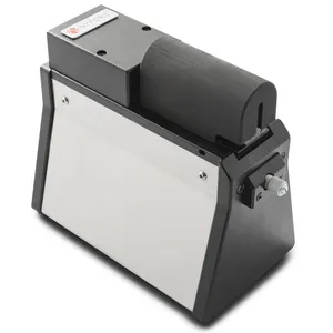
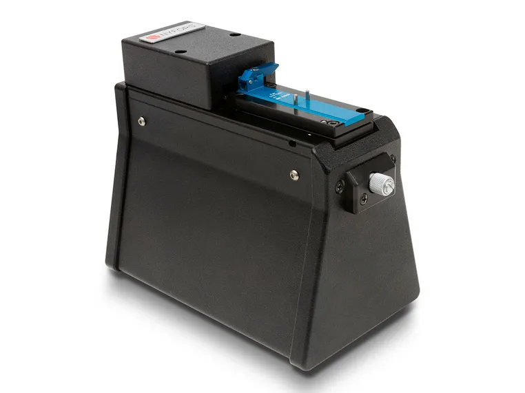
The CLEAVEMETER LIGHT™ comes in a small, ergonomic bench-top design and connects to the USB port of a PC running the host
application.

Technical Data
Fiber cladding
125-800 µm
Fiber coating
250-1500 µm
Camera resolution
1280x1024 pixels
Image scale
1.25 µm per pixel
Image file format
8-bit JPEG, PNG, TIFF, BMP/24-bit BMP for surface topography
PC connection
USB 2.0 port
Power supply
Through USB port
Dimensions
97 mm (W) x 179 mm (D) x 142 mm (H)
Weight
1.6 kg
Absolute accuracy
0.01 degrees standard deviation*
Relative accuracy
5%

* This level of accuracy requires the adaptor plate angle error to be measu-red/compensated for on each individual CLEAVEMETER LIGHT™ the holder is used with. For more information about system accuracy, please contact us at info@nyfors.com.
NYFORS_CLEAVEMETER-LIGHT_sida-
End Face Inspection

CLEAVEMETER LIGHT™

Description

The CLEAVEMETER LIGHT™ is a non-contact interferometer designed for inspecting the end-faces of cleaved or polished optical fibers with cladding diameters of 125 μm to 800 μm. It gives immediate and precise information on important end-face properties such as flatness, perpendicularity, hackles and dust. Based on the NYFORS CLEAVEMETER 3D™ design, in addition to displaying sharp fringe patterns it also generates three-dimensional images of the cleaved fiber end.

When used in this mode, the surface topography is reconstructed from the fringe pattern and presented graphically as a three-dimensional image of the fiber end. By rotating the image and adjusting the scale and contrast, the surface quality and cleave angle at different points can be analyzed in close detail, allowing for a more comprehensive understanding and accurate interpretation of the data and the cleaving process. While this capability is always important to cleave quality analysis, it is especially helpful when analyzing cleaving results of fibers with complicated structures such as polarization-maintaining fibers, or micro-structured fibers. Information on surface topography can also be saved to a file for further analysis using third-party software.

Extremely accurate measurements of both cleave angle and surface flatness over arbitrary diameters can be performed on the reconstructed end-face surface. These measurements are carried out automatically, with full operator independence. This makes the system well-suited not only for detailed cleave quality analysis in laboratory environments but also for close production monitoring where software features such as optional pass/fail indication of cleave angle help ensure that consistent cleave quality is maintained over long periods of continuous cleaving operation.

In addition to cleave angle measurements, the system can also be used to measure a number of other properties such as plane angles, fiber diameters and distance measurements. The software allows the user to view the pointwise slope across the whole fiber end-face, a very useful tool for spotting small scale irregularities and crack propagation behaviour.

Adaptor plates are available for both perpendicular and angled cleave measurements. The mechanical design is compatible with all NYFORS automatic fiber cleavers and accepts the fiber holders used with these tools, as well as those of major splicer manufacturers. Custom-made adaptor plates are available upon request.
The CLEAVEMETER LIGHT™ comes in a small, ergonomic bench-top design and connects to the USB port of a PC running the host
application.

Technical Data
Fiber cladding
125-800 µm
Fiber coating
250-1500 µm
Camera resolution
1280x1024 pixels
Image scale
1.25 µm per pixel
Image file format
8-bit JPEG, PNG, TIFF, BMP/24-bit BMP for surface topography
PC connection
USB 2.0 port
Power supply
Through USB port
Dimensions
97 mm (W) x 179 mm (D) x 142 mm (H)
Weight
1.6 kg
Absolute accuracy
0.01 degrees standard deviation*
Relative accuracy
5%

* This level of accuracy requires the adaptor plate angle error to be measu-red/compensated for on each individual CLEAVEMETER LIGHT™ the holder is used with. For more information about system accuracy, please contact us at info@nyfors.com.

Optical fiber end-face interferometer with 3D topography reconstruction
  • Full resolution surface topography reconstruction
  • 2D view of surface topography and pointwise slope
  • 3D view of surface topography with camera and lighting control
  • Extremely accurate, operator-independent measurements of cleave angle and surface flatness over arbitrary diameters
  • Optional pass/fail indication of cleave angle for fast operation in production environments
Get Quote !
Related products
CLEAVEMETER LIGHT™